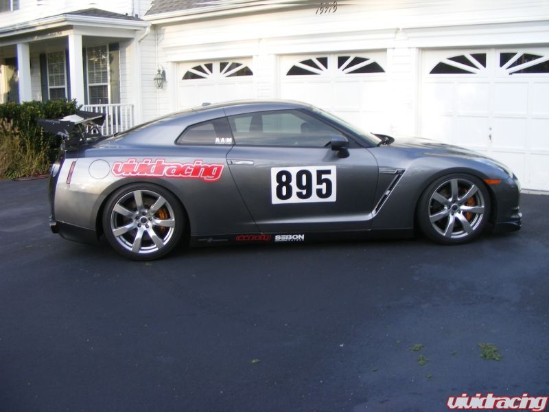
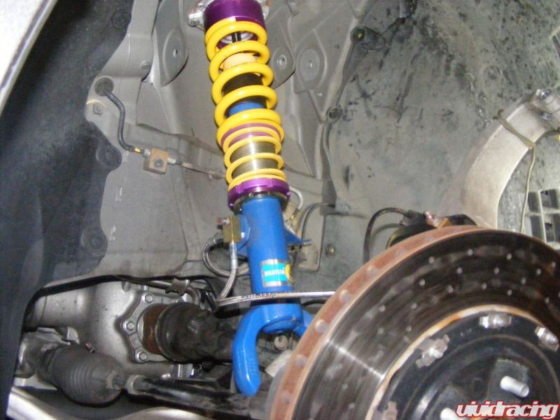
One of our long time customers and online ambassador for Vivid Racing put together this well detailed installation of the KW Sleeve Kit on his 2009 Nissan GTR. Thank you John for the hard work and great information. Very long but detailed post!
Introduction
These are pictures and notes from the installation of the KW Sleeve kit on my 2009 GT-R. These are notes only and are not a comprehensive installation manual. Do not attempt this unless you are experienced at performing suspension work. Compressed suspension springs can be extremely dangerous. Work should be performed in a safe area with a flat and level surface or lift.
By posting these pictures and notes I am not suggesting this is the best way to do this installation and accept no liability as a result of the use of these notes and pictures in performing the installation. In addition, I am in no way affiliated with KW or any other entity.
The car should be placed on four jack stands or a lift. I suggest that you work on one shock at a time. This will allow you to use the other as a reference for reassembly. It also helps to take pictures with a digital camera. Before jacking the car up you should also make some measurements. I measured from the apex of each wheel arch to the top of each wheel. Write these down for later use in determining how much lower you are setting your suspension.
You should also consult the NAGTROC forum for additional input and pictures for this installation.
Front Shock Installation
Picture 1
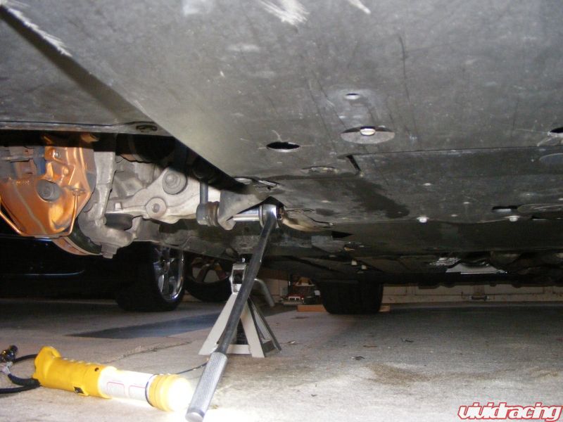
Disconnect sway bar end links.
Picture 2
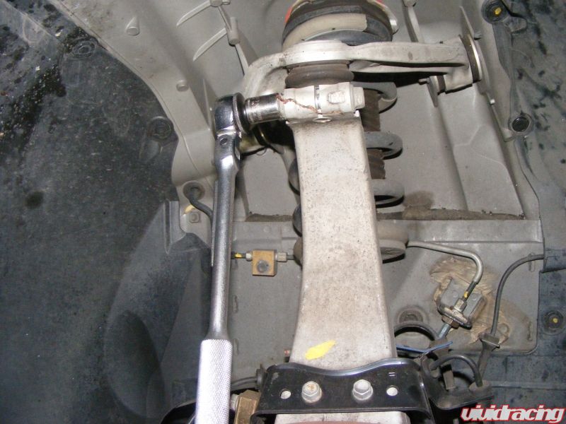
Loosen upper ball joint bolt and remove (joint shaft has cutout to allow bolt to pass thru)
Picture 3
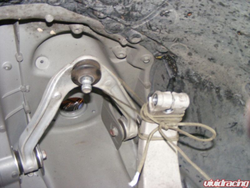
Remove arm from upper ball joint and support with small rope (picture is after shock had been removed). Loosen bolts on upper A arm so that it can be pushed up out of the way. Then attach spring compressors and compress the spring.
Picture 4
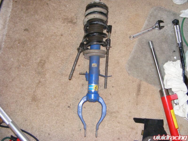
Picture of compressed front spring.
Picture 5
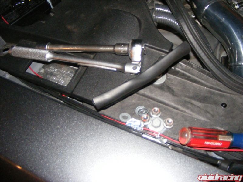
Picture showing engine compartment seal (upper right corner) pulled loose.
Next remove upper shock mount bolts and wire. The wire connects under the plastic panels on each side. You must remove a couple of clips and then pull off the engine compartment rubber seal to lift up the plastic cover (over the battery on passenger’s side, over master cylinder on driver’s side). The wire runs thru a grommet with two other hoses. The grommet is split, after lifting up you can get the shock wire out through the split.
Picture 6
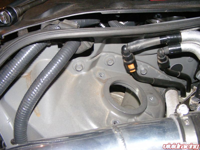
This picture shows the engine compartment seal pulled back and the grommet that the shock wire runs through (grommet is at the top with the two large wire bundles running through it.
Now disconnect the lower shock bolt and allow the steering assembly to slide toward you and forward. Push the upper A arm up as far as it will go. Now slide the bottom of the shock towards the car over the half shaft and tilt the upper end of the shock assembly toward you and out. It will take a little juggling and the inner end of the half shaft may come loose but it will go back in.
Remove the upper shock nut and spring compressors and set the upper mount aside for later use.
Picture 7
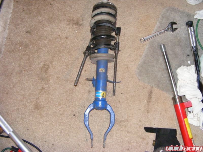
Shock assembly with spring compressed.
Picture 8

Layout of sleeve kit as it will go on the shock.
Picture9
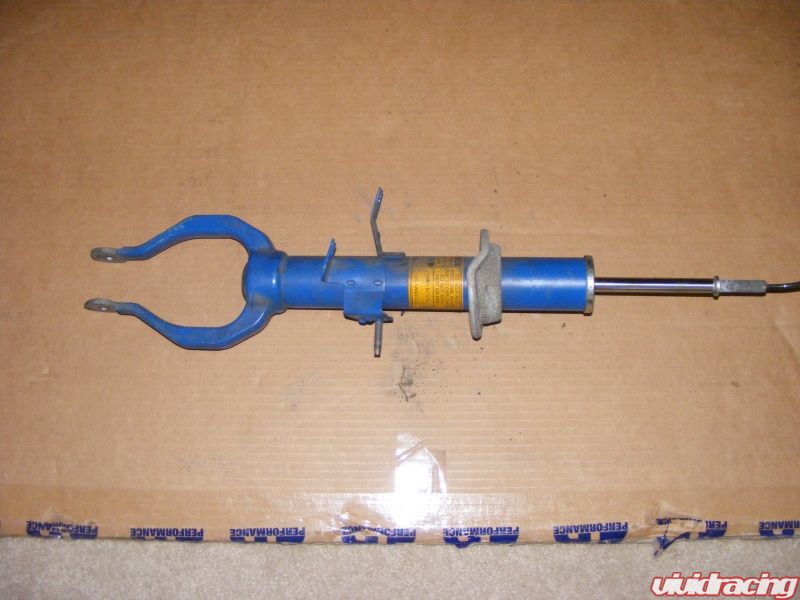
Shock with spring removed.
Picture 10
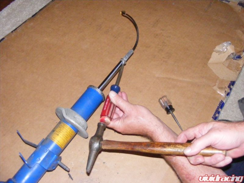
Tap off the washer at the end of the shock rod and the aluminum cap at the top of the shock as shown above.
Picture 11

Using a small hammer slowly tap the OEM spring perch going side to side until it comes off.
Picture 12
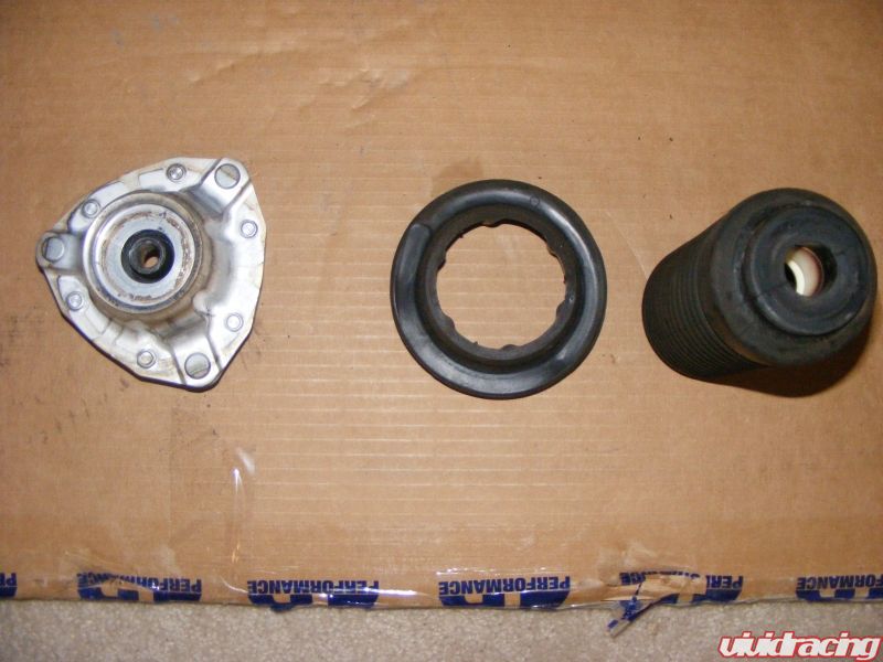
Picture of OEM shock mount, rubber bushing and bellows.
You will only need the actual shock mount shown above on the far left. The rubber bushing and the shock bellows are not needed.
Picture 13
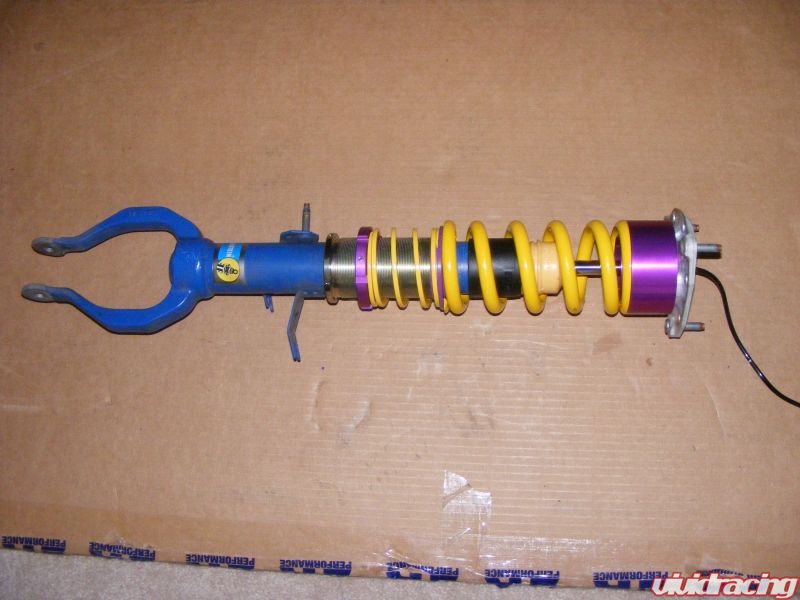
Picture of reassembled shock using the KW sleeve kit in the order previously shown with the OEM upper shock mount attached.
Picture 14
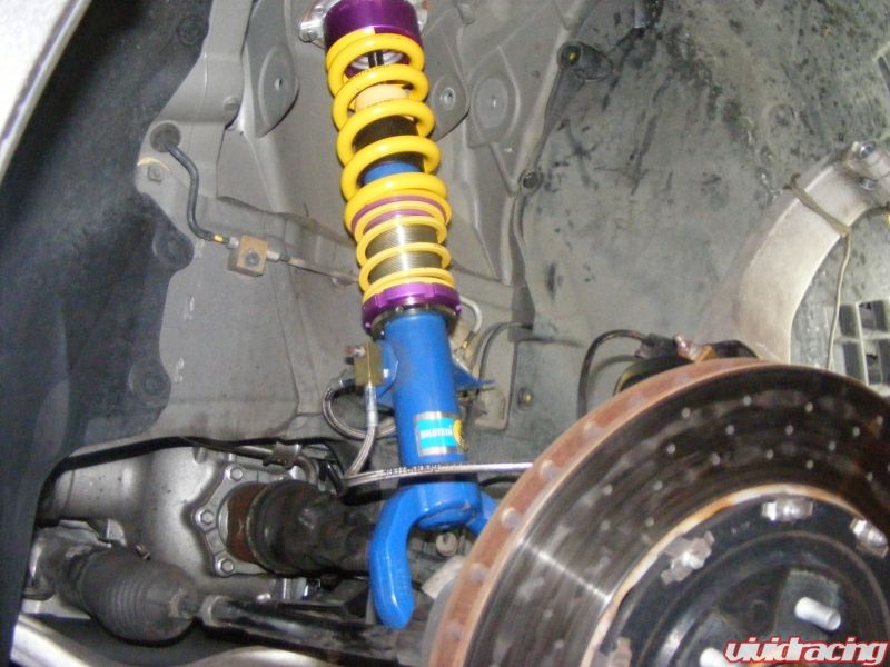
To reinstall the shock assembly reverse the procedure. Put the bottom in first over the half shaft and then tilt the top in under the fender. You will have to push down some on the rotor but it should go in. If no shorten the shock by lowering the lower spring perch. In this picture it has been lowered all the way. With the upper A arm pushed up (note; in this picture the upper A arm has been removed but is not necessary) tilt the top of the shock into position.
Continue the reassembly in the reverse order making sure all nuts and bolts are torqued to the specified level. Before putting the wheel back on use the supplied wrench to raise the lower spring perch. A good starting point is to have 1 ½ – 2 inches between the bottom of the spring perch and the upper side of the lip at the bottom of the threaded sleeve. This should give you about a 1 inch drop.
Rear Sleeve Kit Installation
The rear installation is somewhat easier with the exception of removing the rear interior. This does not affect the drivability of the car so you can work on it over a period of time before removing the shocks.
Start by removing the bottom seat cushions by pulling on the plastic loop under the center of the cushion and pulling up and towards you.
Picture 15
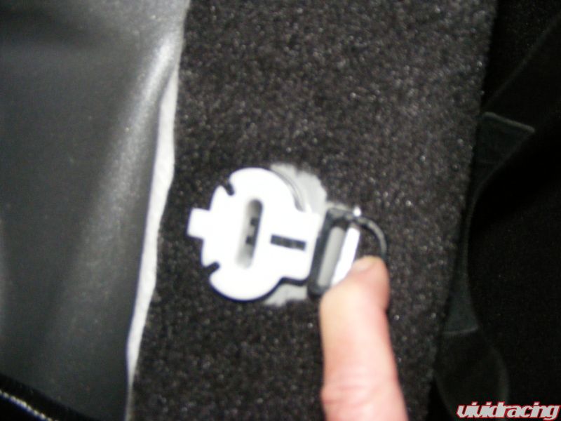
Picture of bottom cushion release tab.
The seat back is attached with one nut at the bottom of the cushion, remove the nut and pull the base towards you and lift up which will release it from the retaining slots at the top.
Picture 16
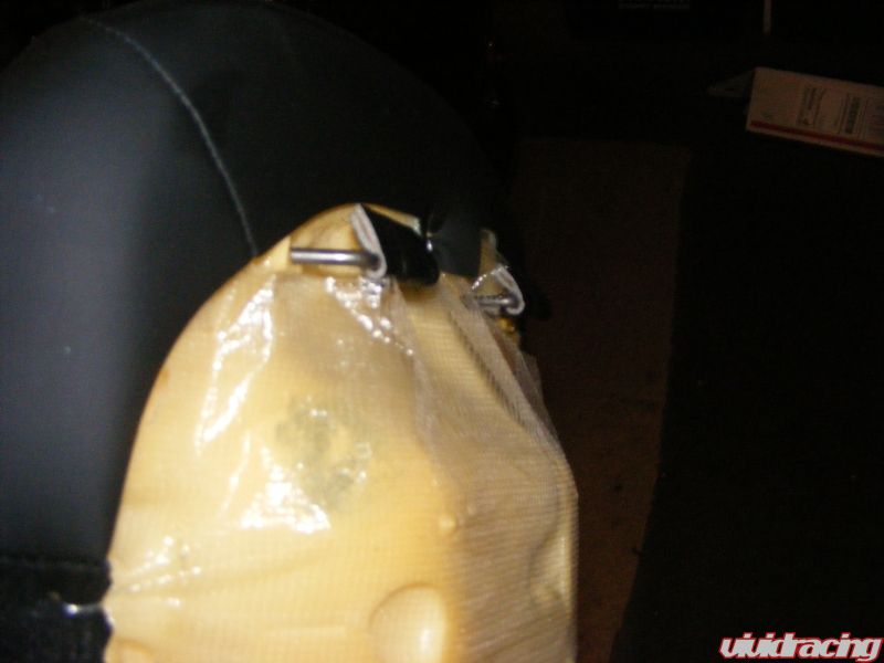
Picture of clips at the top the seat back cushion.
Picture 17

Picture shows the two clips that hold the seat back in place.
Next remove the rear of the center console by pulling up strongly to release the rear clips. Then pull back and up on the console. Turn it upside down and disconnect the wire, or if you will be driving the car unscrew the two screws holding the module to the bottom of the console.
Picture 18
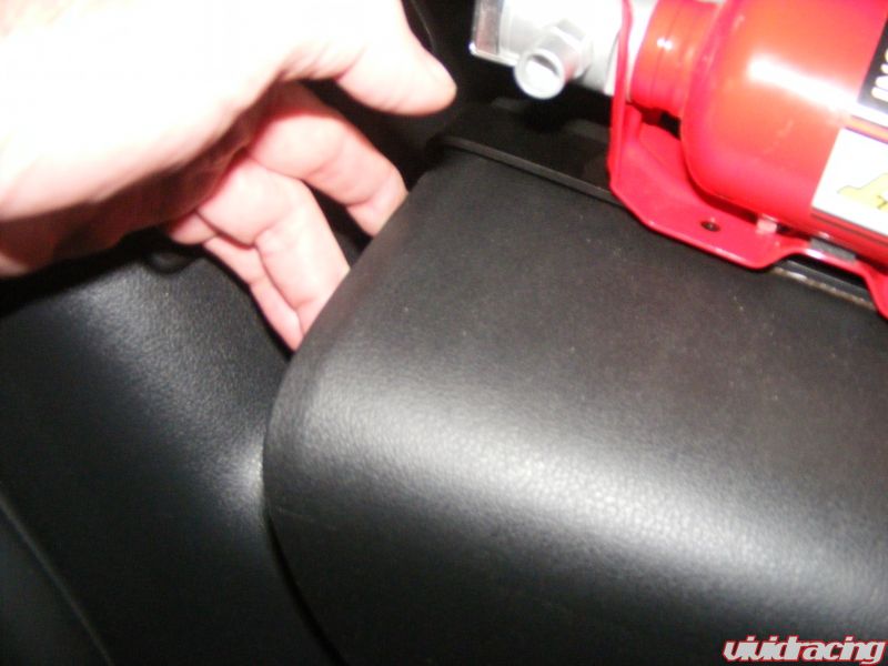
Lifting the back of center console.
Picture 19
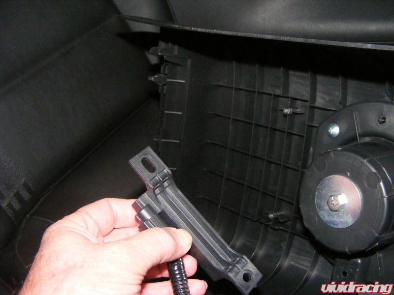
Removing bracket from underside of the console.
Next remove the two bolts at the bottom of the sub woofer cover and pull towards you to release the snap clips that run along the side (see picture below for the location of the snap clips) and remove.
Picture 20
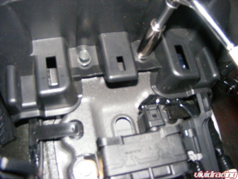
Two lower sub woofer cover bolts.
Picture 21
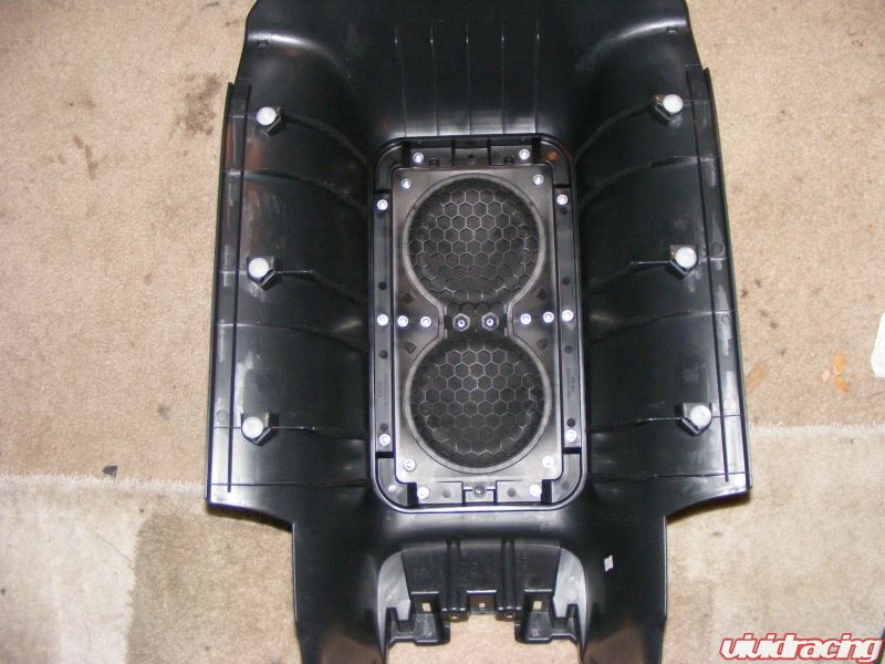
Above is a picture of the back of the sub woofer enclosure showing the location of the snap clips.
Next remove the door sill trim by lifting or prying up from the back. Be careful at the front is a snap clip that releases straight back. Now you can pull lose the door seal all the way up to the roof.
Picture 22
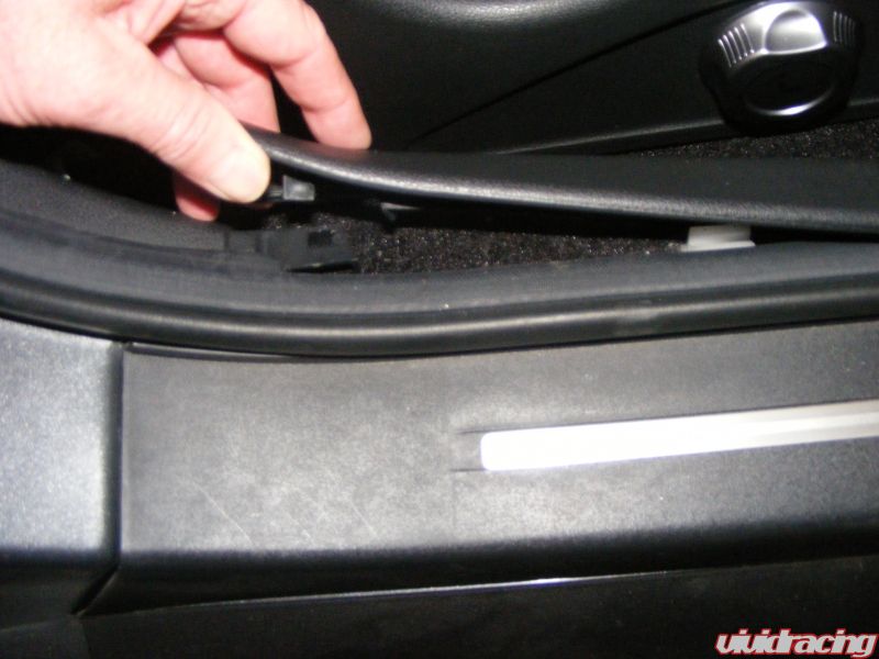
Rear of door sill trim.
Picture 23
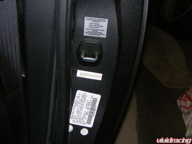
Picture of door seal being removed.
Picture 24
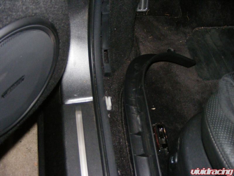
Front of door sill trim.
Now the rear side panels need to be removed. Lift the plastic cover off the shoulder harness upper mount and unbolt. Next remove the screws by the coat hooks on each side.
Picture 25
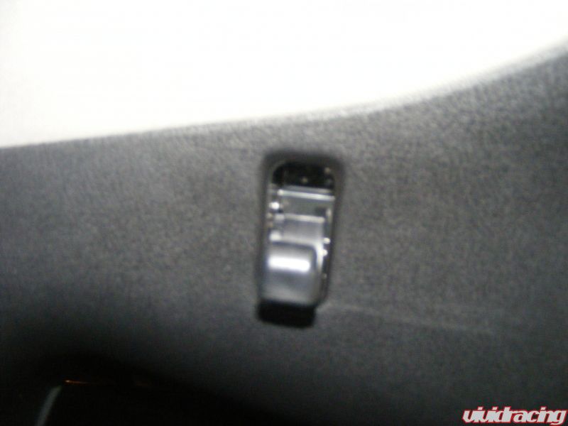
Picture of screw behind coat hook.
Now you can carefully snap loose the upper panel followed by the lower panel.
Picture 26
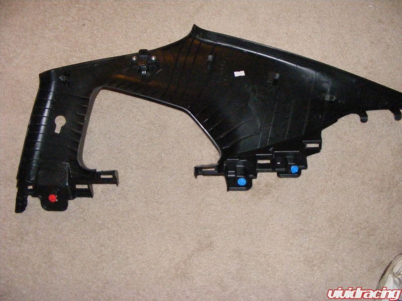
Picture of the back of the upper panel showing the locations of the snap clips (red and blue). Also notice the two plastic tabs at the far right. These will go into slots during reassembly.
Picture 27

Picture of the back of the lower panel showing snap clip locations, two alignment pins and two white clips. During removal some of the clips may detach from the panels and will need to be removed from the car and placed back on the panel.
Picture 28
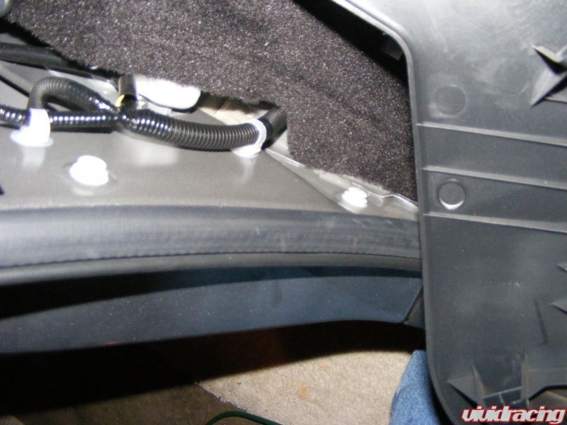
Picture showing two white clips that came off the panel.
Next remove the speaker shelf cover. There are four Phillips head plastic retainers. They are not really threaded but unscrewing them does work, if not pry the head out and then the rest of the clip. You should be able to lift and pull the shelf towards you and let it lay down.
Picture 29
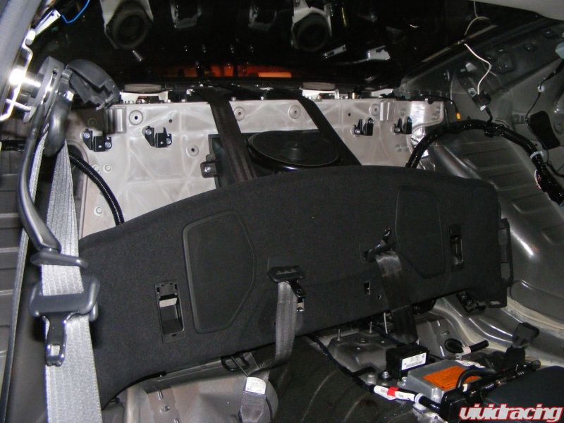
Picture of rear shelf, just leave it as shown.
Now remove the foil covered insulation in each corner. Peel it off slowly so that it can be reused. I would suggest having a piece of freezer paper handy to put them on as they are very sticky.
Picture 30
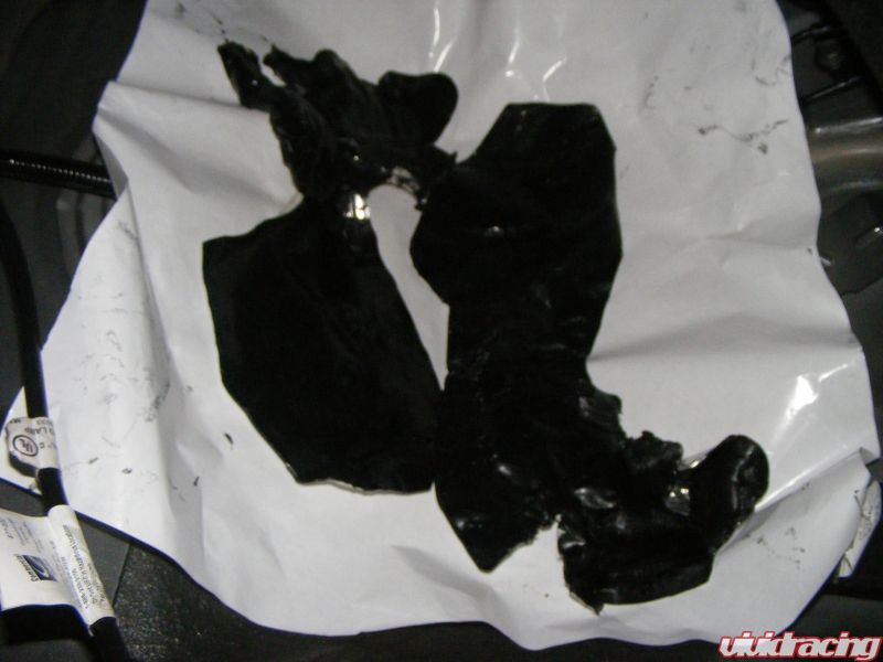
Picture of insulation on freezer paper.
At this point the car is still drivable, the next step is to get it back up on jack stands and remove the rear wheels.
Disconnect the shock wires and loosen the three shock mounting bolts on each side.
Picture 31
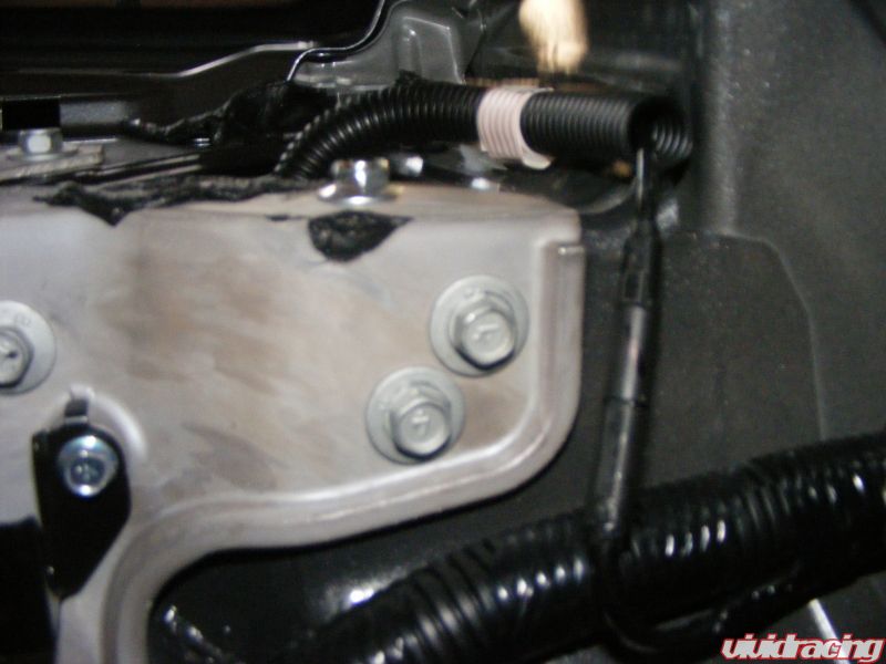
Picture of shock wire connection.
Picture 32
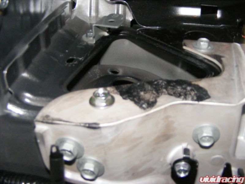
Picture looking down into where the shock mounts.
Now remove a rear wheel and disassemble the lower shock mount the same as was done in the front. Disconnect the sway bar ends first then unbolt the bottom of the shock and compress the spring.
Picture 33
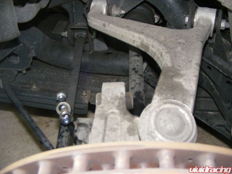
Picture of sway bar link disconnected (I have the COBB link). Shock had already been removed in this picture.
Once you have the shock out follow the instructions for the front shocks to remove OEM parts and replace with the KW parts.
Picture 34
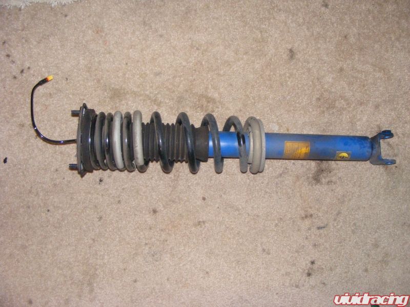
Picture of rear shock before disassembly.
Picture 35
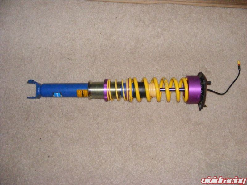
Assembled rear shock.
Now unscrew the lower spring perch as far as it will go and reinstall the shock making sure everything is tightened to spec. I would then raise the lower perch until there is 1 ½ – 2 inches between the bottom of the spring perch and the upper edge of the bottom of the sleeve.
I would suggest driving the car around for several days before putting the interior back in so that you can re-tighten the upper shock mount nuts. It is a good idea to recheck everything at this point.
Just reverse these instructions to reinstall the interior. While the interior is out you might want to install sime insulating material.
Additional Pictures
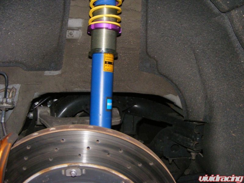
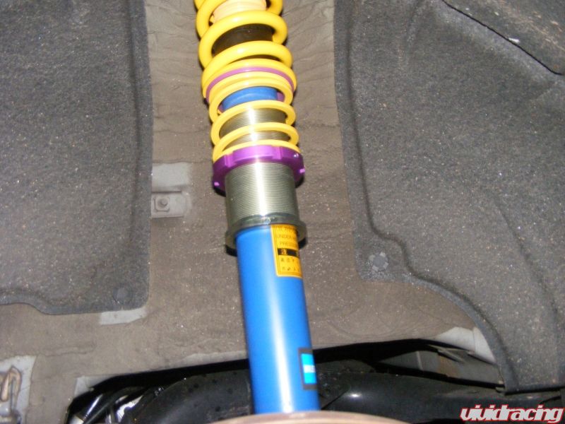
Thoughts on the KW Sleeve Kit
Although I have not had a chance to test them on the track I live in an area that has a good combination of roads. This includes long high speed straight a ways, high speed turns, banked turns, slow speed turns and the regular stop and go of a commute.
This has given me the opportunity to work the KWs pretty hard and soft. On an average road I really don’t notice any difference just driving along. On bumpy roads at speed they do become harsher as you get into the stiffer part of the spring. In turns, particularly at speeds the car feels taught and planted to the road more than the OEM springs. This provides you with an added level of confidence during turn in with little if any push.
The other advantage of the sleeve kit is it’s allowance for height adjustment. After reading up on the subject on the NAGTROC forum it seems that a 1 inch drop is the maximum without upsetting the suspension geometry. However, for normal street driving I am sure you can get a 2 inch or more drop. This will take some of the preload out of the spring and I don’t know how that would affect the cars handling.
Setting Your Ride Height
In setting your ride height, first drive your car around for a few miles make left and right turns then recheck your mounting bolts. Now measure the car the same way you did at the start and determine the difference. Using the supplied tool screw in the lower spring perch (left to right) 3 to 4 turns at a time to raise the car, and unscrew (right to left) to lower. Write down the number and direction of turns. Now drive the car around making left and right turns to reset the suspension. Measure the ride height again and adjust accordingly. It may take several times but you will get there.
Now go drive the car the way it was built to be driven.
I would like to thank Vivid Racing for getting me the kit both quickly and at a very reasonable price. I have been getting most of my parts from Vivid for the past several years, not just for the GT-R but for my NSX as well. They have a great team there and seem to have the best prices I can find on parts. They have also provided me with excellent customer service, and in the few cases where I had an issue with something they really stepped up to get it resolved to my satisfaction.
I highly recommend them for aftermarket parts regardless of the type of car or the parts manufacturer. They seem to work with all of the major after market and high performance parts manufacturers including their in-house Agency Power line.
Give them a call at 866-44-Vivid (866-448-4843).
